
Cooling water pipelines are the lifelines in nuclear power plants and occur in three main cooling water circuits in reactors of the pressurised water type, which accounts for about 90% of the reactors in operation worldwide. In addition, there are emergency and auxiliary cooling systems.
The purpose of a cooling water system is basically to absorb and dissipate excess heat so that functionally relevant plant components do not overheat. The primary circuit is located in the so-called "containment" in the reactor building. This consists of the reactor pressure vessel, the primary coolant pumps and the steam generators, including the piping system. This means that in this "containment" the coolant water has direct contact with the fuel rods.
Via the secondary circuit, live steam is then fed through the steam generators from the "containment" to the steam turbines. However, for a steam turbine to be able to convert the heat of the supplied steam into mechanical motion, the temperature and pressure differences upstream and downstream of the turbine must be as great as possible. Therefore, after leaving the turbine, the steam is cooled down via a heat exchanger, also called a condenser, to such an extent that it condenses back to liquid water and flows back to the steam generator in the primary circuit as feed water. There, the recirculated water is heated again and returns to the turbines as steam.
Separate cooling pipes are fed to the heat exchanger to cool the steam - the third cooling circuit. The water in this cooling circuit flows from the heat exchanger to a cooling tower and back again. In the cooling tower, the water heated in the heat exchanger is distributed, and the falling water droplets give off heat to the passing air currents in the cooling tower (chimney effect).
This is the general process during normal operation. As briefly mentioned above, there are other cooling systems. While the main cooling water serves to cool the "conventional" circuits on the secondary side during operation, the heat absorbed by the "nuclear" primary circuit and the fuel rod storage pool, among others, is transferred to the auxiliary cooling water and the redundant emergency cooling systems via various intermediate cooling systems when the plant is shut down.
Main and auxiliary cooling water is taken from a river or the sea and fed to its intended purpose via purification as well as treatment plants. These inlets- and distribution pipes up to the purification as well as treatment plants usually have an inner coating of rubber, the integrity of which must be verified by visual inspection at regular intervals, especially in older power plants.
Detailed interior views of the pipe live and in colour
However, before it can start, an inspection specification must be drawn up in advance, which describes the basic procedure of the visual inspection. This must be checked and approved by the operator of the power plant and an expert. Afterwards, the performance of the visual inspection and its sequence is the responsibility of head of operations. The inspection personnel deployed are qualified and certified in level VT2 according to DIN EN ISO 9712, an application guideline for the performance and evaluation of visual inspections.
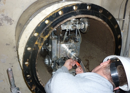
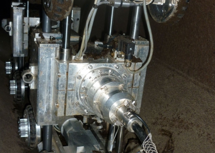
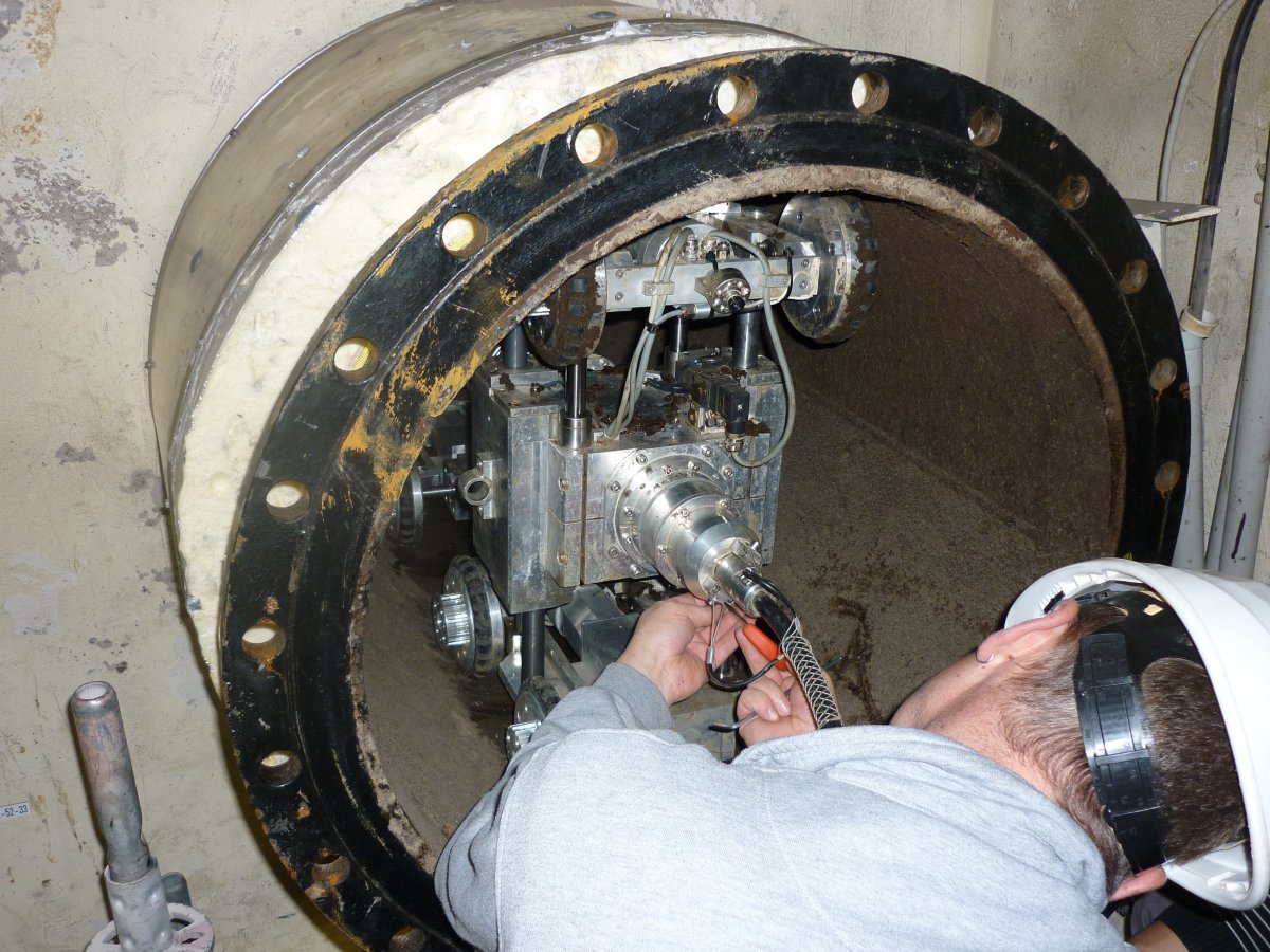
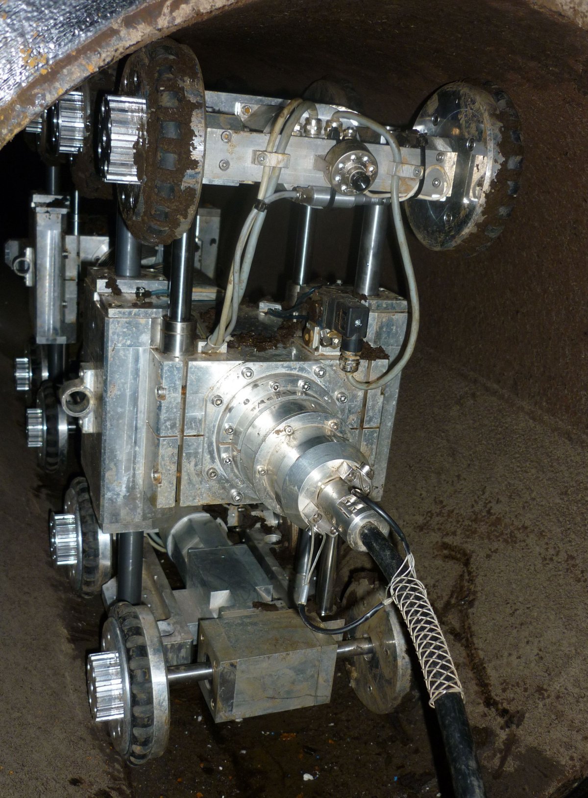
In the following, the test covered an approx. 90-metre-long DN 300 rubber-lined cooling water pipe with a total of four bends and an approx. 170-metre-long DN 700 rubber-lined cooling water pipe with a total of three bends. Two visual inspection robots from INSPECTOR SYSTEMS were used, one of type 4.000 (ID 180 to 325 mm) and one of type 6.000 (ID 440 to 750 mm), each with a high-resolution colour camera and 10x optical zoom as well as automatic/manual focusing.
After the control components and the inspection robots were set up, a function test was carried out. To prove the image quality, standardised comparison panels were used in advance and the cameras were then calibrated accordingly. By integrating them into a pan/tilt module, the cameras can be rotated by 360° and tilted by 110° so that every part of a pipe surface can be clearly examined.
The illumination direction to the test object and to the optical axis can be selected in such a way that an optimal image contrast is created. By varying the illumination intensity and the variable views from different directions, disturbing reflections and shadows can be avoided, thus making an optimal observation of conspicuous features possible. The evaluation took place simultaneously with the visual inspection and after the end of the inspection by viewing the recorded data.