Correction of pipe welds to prevent cable damage
The transition to a carbon-free future is gathering pace thanks to the further development of the energy infrastructure. The expansion of renewable energies plays a central role compared to the use of fossil fuels. Renewables are almost inexhaustible. Their production causes little to no climate-damaging greenhouse gas emissions. The earth offers considerable potential for generating renewable energy, e.g. with the help of the sun, water and wind. With wind energy, air currents are converted into electrical energy.
This is done by means of a wind turbine. A tubular tower with a three-bladed wind turbine mounted at the top that uses the air flow to drive a generator. The installation of a wind turbine was first documented in 1883 on the occasion of an electricity exhibition in Vienna, Austria. At that time, the wind turbine had a diameter of just 7 meters and a modest efficiency of merely a few kilowatts, whereas the largest turbine currently in use has an "incredible" diameter of 260 meters and an output of 16 megawatts - and the trend is rising.
Tailwind for the energy transition
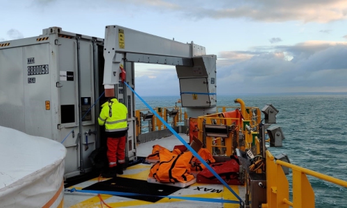
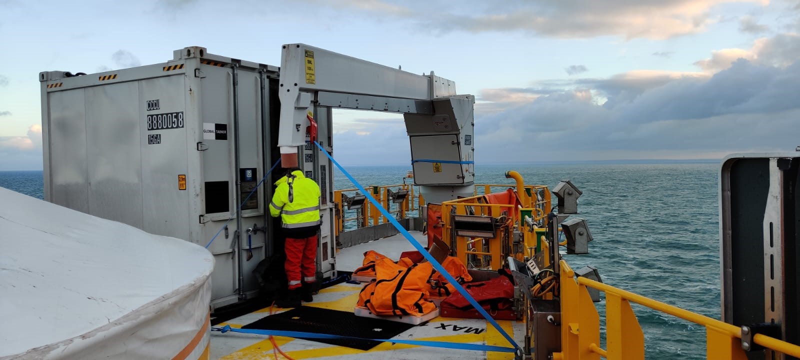
The wind farm operator turned to INSPECTOR SYSTEMS in order not to jeopardize the strictly coordinated series commissioning of more than 60 wind turbines in an offshore wind farm off the coast of north-west France. The reason for this was the inconsistent quality of the welded joints within special offshore cable tubes. A correction was necessary so that the connecting cables could not be damaged by sharp edges when being pulled through. INSPECTOR SYSTEMS has a lot of experience with similar projects from the past. The individual foundations of the wind turbines consist of a triangular construction made of steel pipes, the so-called jacket type, the upper end of which protrudes out of the sea after installation.
Depending on the design and use, one to three offshore cable tubes are integrated into each foundation - known as a jacket tube or J-tube. These are used to connect the cable network of the wind turbines to the transformer station, which is also located in the offshore wind farm, before the generated energy is fed into the onshore grid via an underwater cable. As each J-Tube consists of pieces of pipe welded together and can therefore contain up to nine weld seams over a total length of 60 to 70 meters, there is a potential risk of damage to the cable at each weld seam when it is pulled in. In other words, a single root protrusion or a sharp edge can mean the failure of an entire wind turbine with subsequent high repair costs.
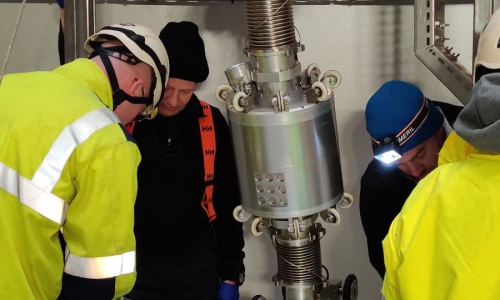
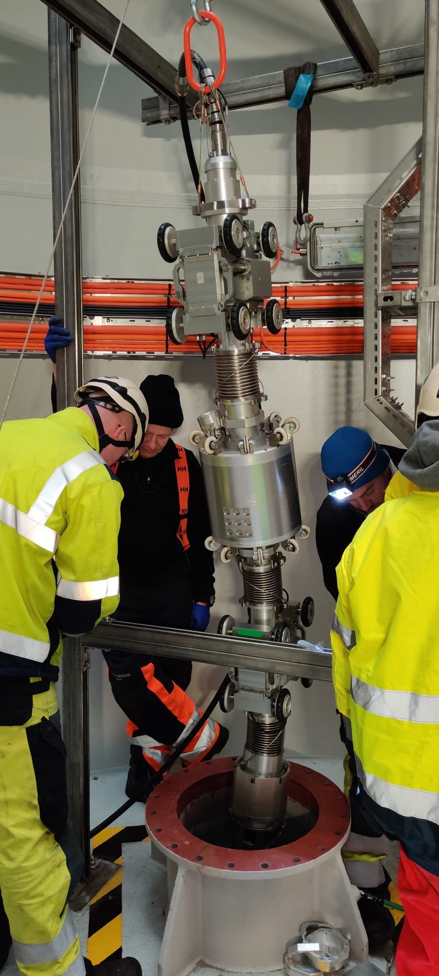
Combined robot for grinding, laser measurement and visual inspection in use
The customer's specification was that each weld seam must not have an protrusion of more than two millimeters or a sharp edge. Weld seams that did not fulfil this requirement had to be corrected until the specifications were met. As over a third of the more than 60 jackets had already been installed, the correction and testing work first took place at sea and then at the onshore production site. A combined robot for pipe diameters of 12 to 20 inches from INSPECTOR SYSTEMS was used, whose grinding unit is equipped with a laser measuring system on a 360° rotation unit in addition to a visual camera. Combining different operations in just one robot increased the efficiency of the entire work process.
Two drive units with their pneumatically extendable wheel carriers were responsible for clamping and stabilizing the entire robot inside of the pipe. Despite the harsh marine environment and wet pipe surfaces, this made it possible to reach every single weld seam vertically, with the furthest being around 70 meters away. The additional clamping system of the grinding unit ensured safe and stable positioning during the work process.
Once the weld seam had been reached, it was visually inspected for particularly damaging edges. In addition the laser measuring system determined the highest point of the weld seam in a 360° circumference. Depending on the result, the weld seam joint was then processed. This process was carried out by the grinding unit and its main component, a grinding motor with variable speed control. Thanks to the additional axial and radial stroke system, the adapted grinding wheel was able to process every area of the weld seam in width and height with an accuracy in the tenth of a millimeter range until sharp-edged areas were removed and the root protrusion was less than 2 mm all round. Verification was again carried out using the visual camera as well as the laser measuring system and was documented.
Almost 80% of the approx. 1,000 weld seams required treatment. This was a particular logistical challenge, which was met to the customer's complete satisfaction together with a partner company.